COMPONENTS. CONNECTIONS. POSSIBILITIES.
Built around
your next flight.
UAV components, robotic actuators and airspace monitoring. Find the hardware. Bring your project forward.
120Products & series
13Component brands
01Place to source
ENGINEER YOUR NEXT BUILD01 / COMPONENTS
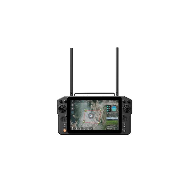
COMMUNICATION & CONTROLSkydroid H30
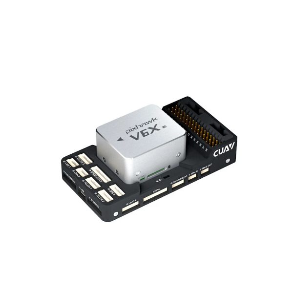
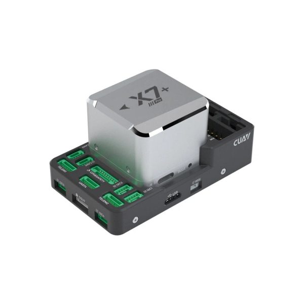 FLIGHT CONTROLLERSCUAV X7+ Pro
COUNTER-UAS · AI VISION
See more.
Track intelligently.
Counter-UAS AI Vision Module
Compact onboard perception for UAV vision and flight-controller integration. Built-in AI algorithms combine full-frame object recognition, tracking and motion prediction.
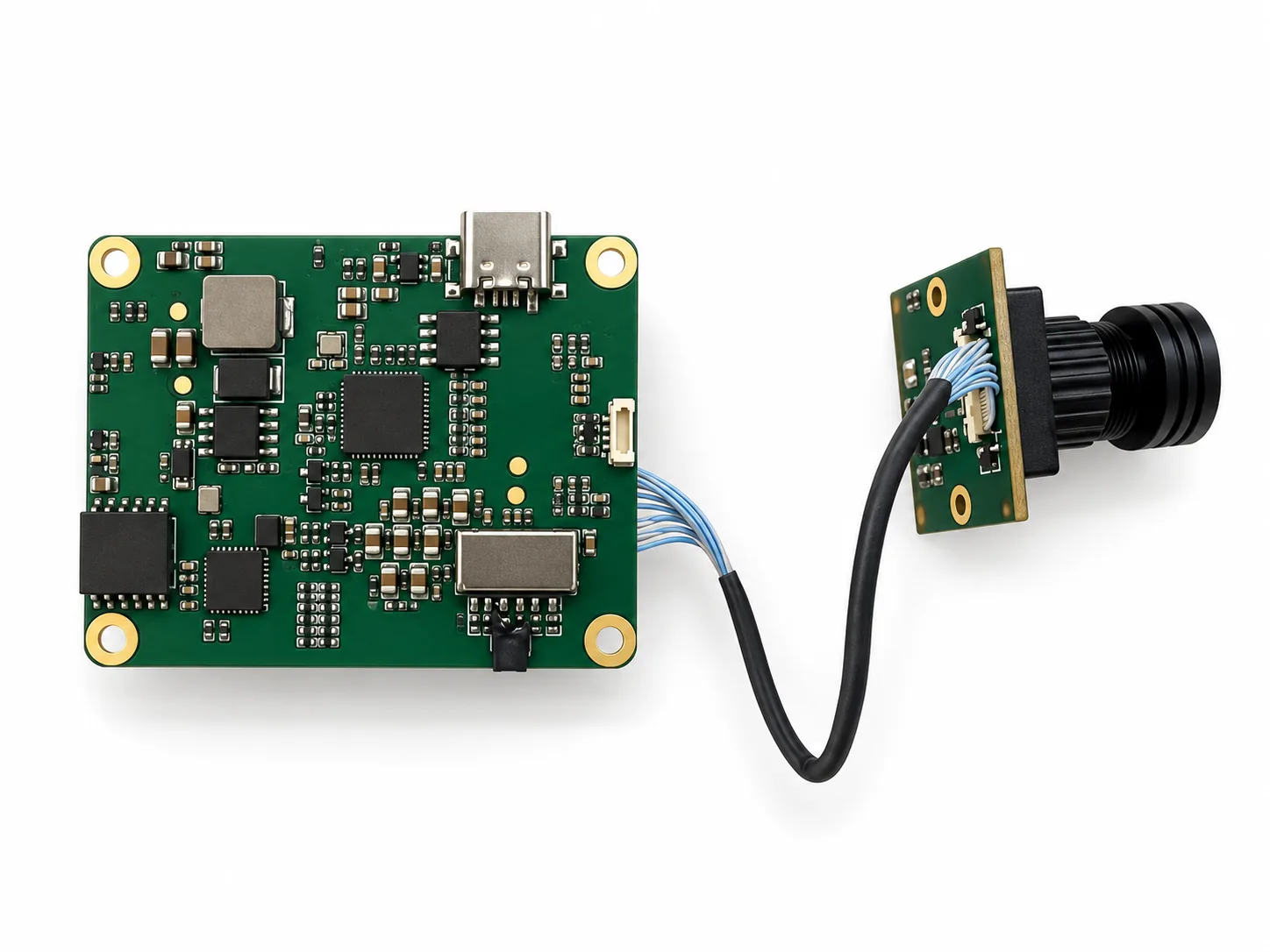
6 TOPSAI computing power
1080pFull-frame recognition
110 fpsRecognition & tracking output
4 GB / 32 GBMemory / storage
ONBOARD PERCEPTION
Vision data.
In step with flight.
The module integrates edge AI recognition, tracking and motion prediction. GPS-fused vision and multi-sensor processing support the perception workflow, with infrared available as an option.
Serial output provides structured object information, including position, class, confidence and recognition-box timestamps. Time synchronization helps align visual observations with flight-state data.
Matching flight-controller firmware is supplied for ready-to-use integration.
- 01
Full-frame vision
Recognizes and tracks objects across the full 1920 × 1080 input image.
- 02
High-frequency output
Supports 110 fps recognition and tracking output at the same frequency.
- 03
Multi-sensor perception
GPS-fused vision processing, with infrared and other data sources available as options.
- 04
Time-aligned data
Recognition-box timestamps support synchronization with flight-controller time to align visual data and flight-state information.
- 05
Motion prediction
Combines object-motion information and aircraft state to predict object position. One algorithm covers different speeds and stationary or moving objects.
PRODUCT DEMONSTRATION
From hardware to live vision.
Read the video overview
The demonstration introduces the AI vision module, its 6 TOPS computing power and 4 GB / 32 GB memory and storage. It shows camera and interface connections, UAV installation and full-frame recognition footage. On-screen supplier claims include 1920 × 1080 full-frame recognition, 110 recognitions per second, approximately 98% recognition performance and approximately 1 ms alignment delay between object information and flight-controller data. These figures are not independently verified and the source does not specify test conditions.
TECHNICAL SPECIFICATIONS
Compact hardware.
Detailed capability.
Specifications follow the supplied product page. Performance values are supplier-stated; the source does not specify test conditions.
- AI computing power
- 6 TOPS
- Memory / storage
- 4 GB / 32 GB
- Input resolution
- 1920 × 1080 (1080p), full frame
- Recognition rate
- Supports 110 fps
- Tracking output
- 110 fps, at the same frequency as recognition
- Minimum recognition size
- 3 × 3 pixels
- Recognition performance
- Approximately 98% — supplier-stated; test conditions are not specified.
- Field of view
- Approximately 43.0° × 25.5°
- Board dimensions
- 52 × 40 mm
- Height, excluding lens
- 19.5 mm with heatsink; 7.5 mm without heatsink
- Weight
- 21 g without heatsink; 46 g including heatsink and camera
- Flight-controller support
- Native Betaflight compatibility; matching flight-controller firmware supplied
- Control interface
- 3.3 V TTL serial
- Video output
- 100 Mbps Ethernet camera stream and CVBS
- Structured serial data
- Object position, class, confidence and recognition-box timestamp; object-offset output
- Perception options
- GPS-fused vision; optional infrared and other data sources
HARDWARE INTERFACES
Connections, clearly defined.
View connector definitions & pin assignments
100 Mbps Ethernet · PH1.0-4PIN
Camera video-stream output.
| Pin | Signal | RJ45 pin |
|---|---|---|
| 1 | TX+ | 1 |
| 2 | TX− | 2 |
| 3 | RX+ | 3 |
| 4 | RX− | 6 |
Serial + power · PH1.0-9PIN
UART11_M1 outputs object offsets. UART4_M0 currently has no function.
| Pin | Signal | Definition |
|---|---|---|
| 1 | 9V–40V | Power input. Reversing polarity will damage the module. |
| 2 | GND | Power ground |
| 3 | UART11_TX_M1 | 3.3 V TTL serial output; connects to the flight controller |
| 4 | UART11_RX_M1 | 3.3 V TTL serial input; connects to the flight controller |
| 5 | GND | Serial ground |
| 6 | UART4_TX_M0 | 3.3 V TTL serial output; leave unconnected |
| 7 | UART4_RX_M0 | 3.3 V TTL serial input; leave unconnected |
| 8 | CVBS-GND | CVBS video ground |
| 9 | CVBS | CVBS video output |
USB-C
USB 2.0 firmware-flashing port.
USB 2.0 infrared thermal-imaging port
| Pin | Signal | Definition |
|---|---|---|
| 1 | 5V | 5 V / 1 A power output |
| 2 | GND | Ground |
| 3 | DP | USB signal |
| 4 | DM | USB signal |
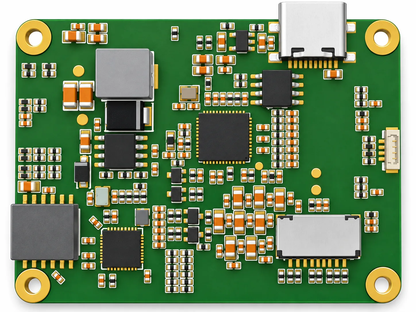
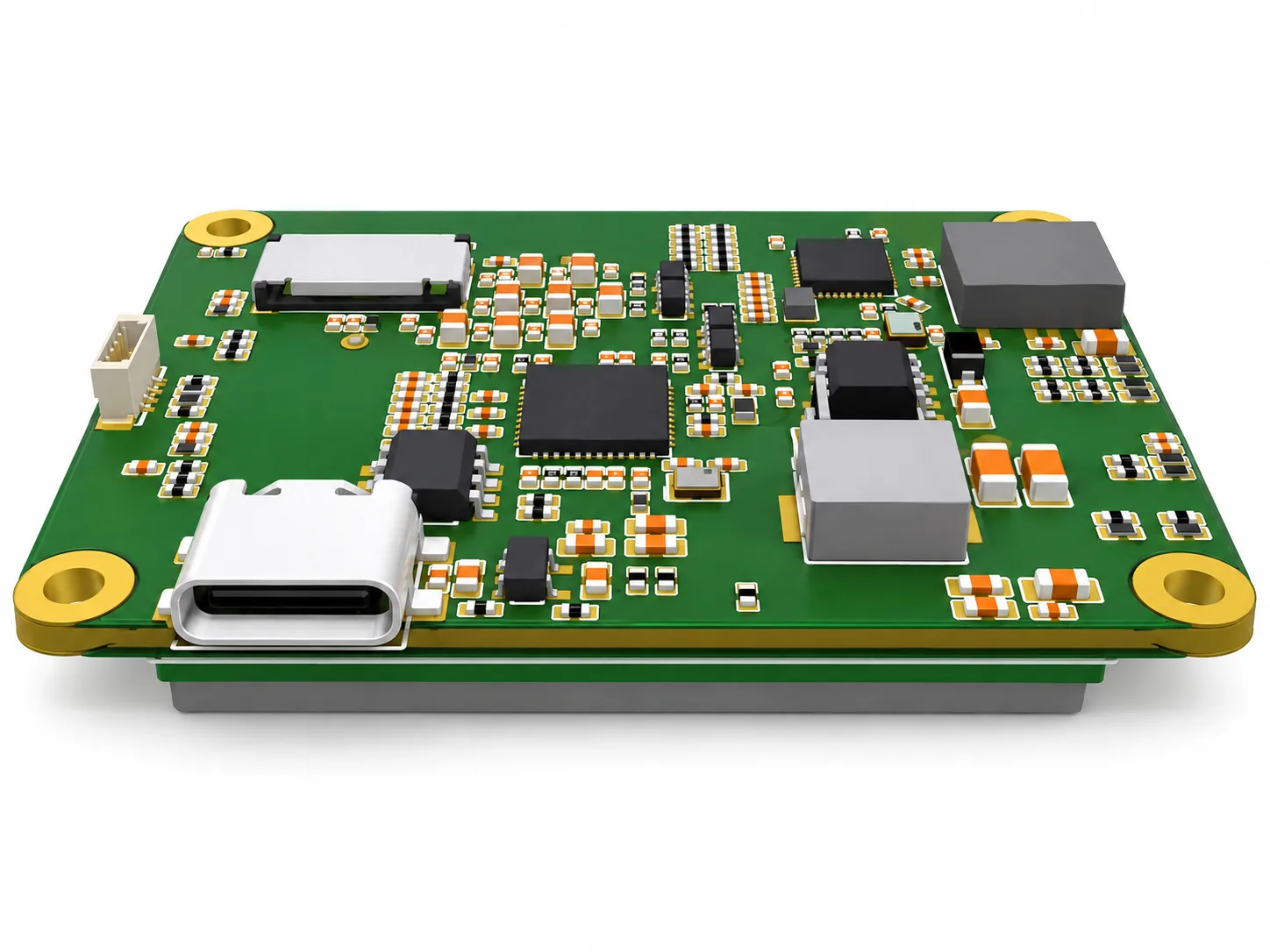
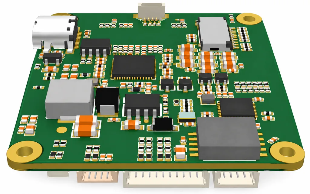
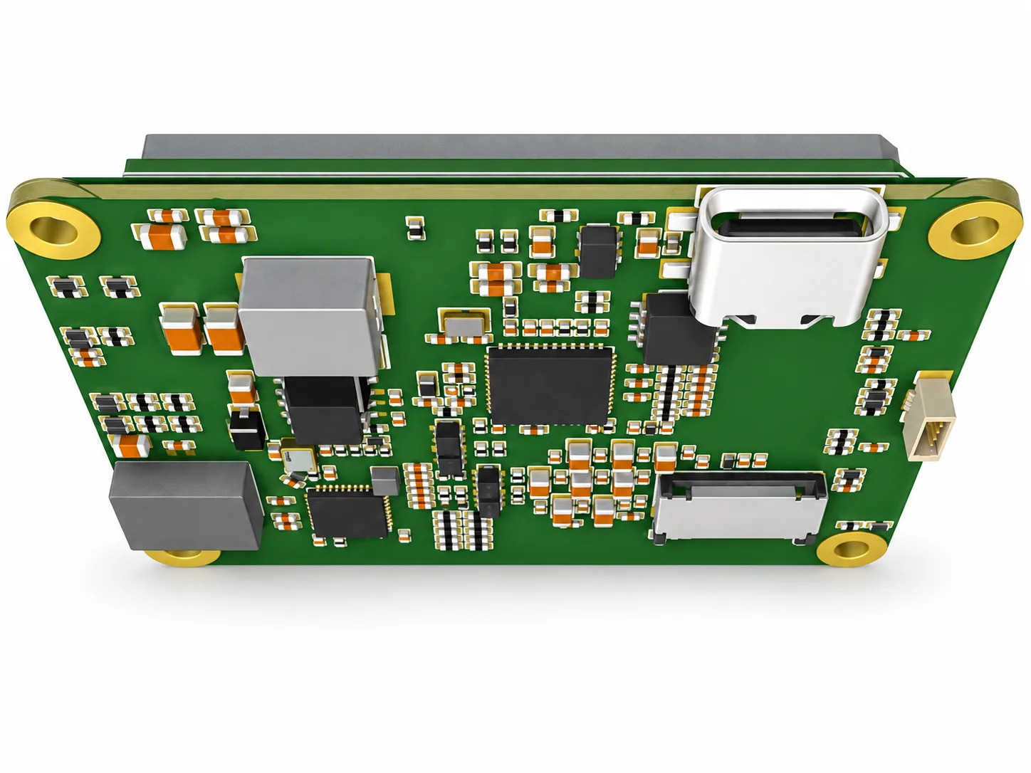
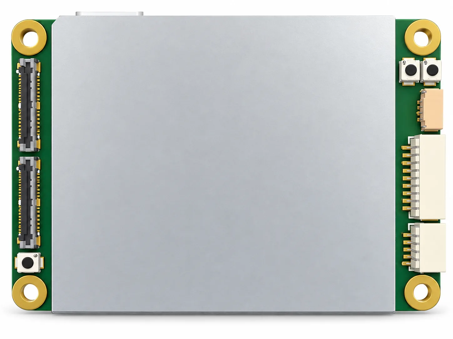
PRODUCT VIEWS
A closer look at the module.
DISCUSS YOUR APPLICATION
Bring your vision requirements.
Share your flight controller, camera or infrared requirements, quantity and destination.
FIND YOUR STARTING POINT
Every part has a purpose.
01
Flight & navigation
Flight controllers, GNSS and sensing.
02
Propulsion & power
Motors, ESCs, propellers and batteries.
03
Communication & control
Data links, ground stations and FPV.
04
Cameras & payloads
FPV cameras and stabilized imaging.
05
Robotics
Actuators and gimbal motors.
06
Flight safety
Parachute systems and accessories.
FROM THE CATALOG